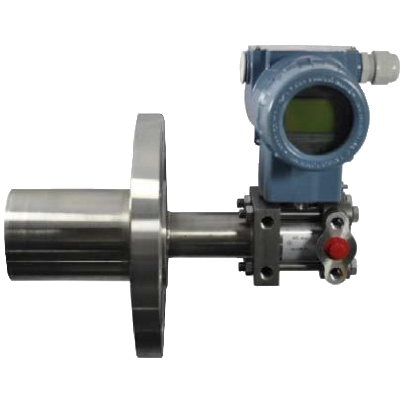
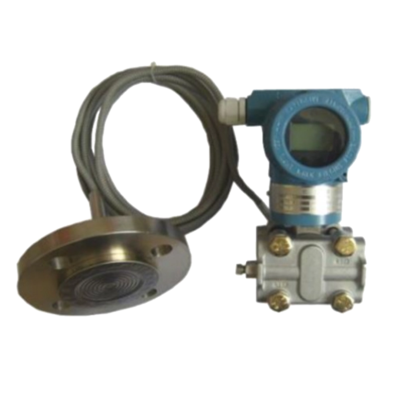
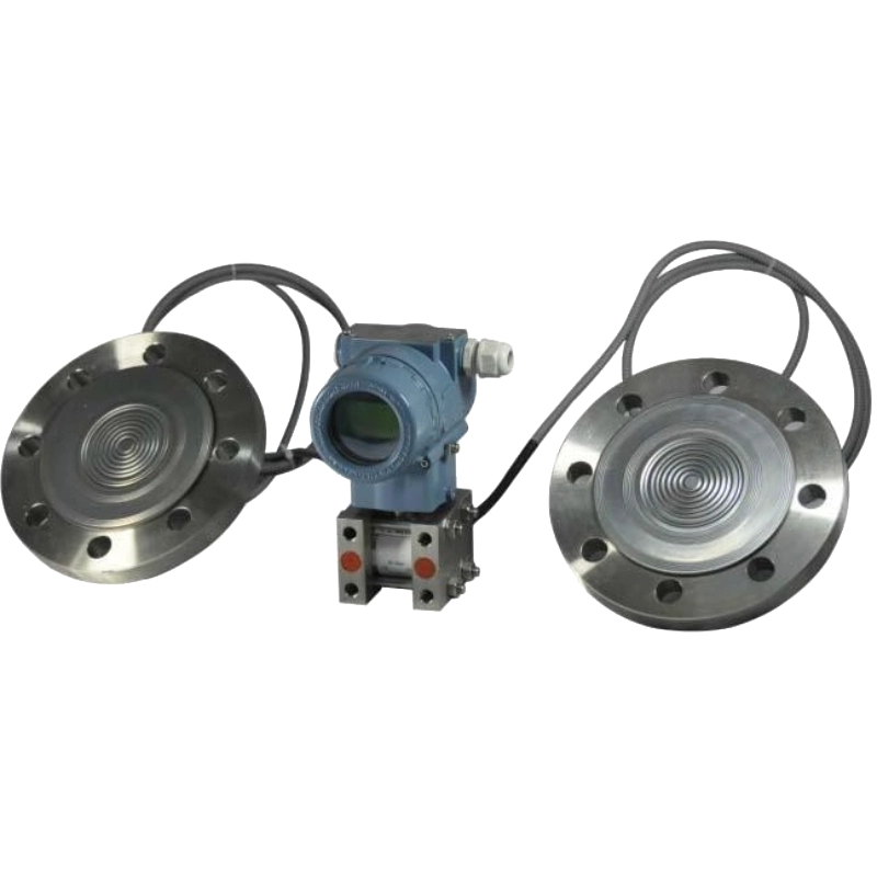
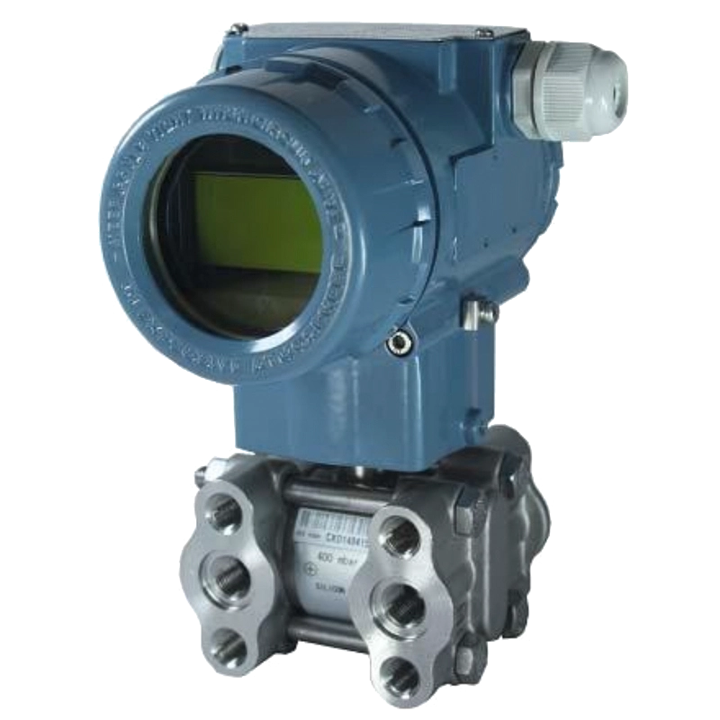
The SM39PWB-CY differential pressure transmitter is used to measure the liquid level, density, pressure, and flow rate of liquid, gas or steam, and then convert it into 4 mA to 20 mADC HART current signal output. It can also communicate with HART handheld terminal for parameter setting, process monitoring, etc.
Differential pressure sensor side-mounted performance requirement
Reference accuracy of scalrange (including linearity, regression, and repeatability from zero):
± 0.0 7 5% If TD> 10 (TD= maximum range / adjusted range) is: ± (0.0075 TD)%
| Quota code | -20℃ to 65℃ for the total effect amount | Quota code | -40℃ to-20℃ and 65℃ to 85℃ total effects |
| A | ±(0.45×TD+0.25)%×Span | A | ±(0.45×TD+0.25)%×Span |
| B | ±(0.30×TD+0.20)%×Span | B | ±(0.30×TD+0.20)%×Span |
| C/D/F | ±(0.20×TD+0.10)%×Span | C/D/F | ±(0.20×TD+0.10)%×Span |
The square root output accuracy is 1.5 times the above linear reference accuracy. The influence of ambient temperature
Over the scope of influence
±0.075%×Span
Static pressure effect
| Quota code | influence quantity |
| A | ±(0.5%Span)/4MPa |
| B | ±(0.3%Span)/16MPa |
| F/ G/H/I/J | ±(0.1%Span)/16MPa |
D Overpressure effect
| Quota code | influence quantity |
| A | ±0.5%×Span/4MPa |
| B/C/D/E | ±0.2%×Span/16MPa |
| F/ G/H/I/J | ±0.1%×Span/16MPa |
long term stability
| Quota code | influence quantity | |
| A | ±0.5%×Span/1 | year |
| B | ±0.2%×Span/1 | year |
| F/ G/H/I/J | ±0.1%×Span/1 | year |
Power impact
± 0.001% / 10V (12 to 42 VDC), negligible.
Differential pressure sensor side-mounted functional specification
Range and range
| Range / range | kPa | |
| A | range | 0~1 |
| scope | - 3000~ 3000 | |
| B | range | 1~ 100 |
| scope | - 1 6 000~ 1 6 000 | |
| C | range | 100~ 500 |
| scope | - 1 6 000~ 1 6 000 | |
| Д | range | 500~ 3000 |
| scope | - 1 6 000~ 1 6 000 | |
| E | range | 30 00~ 4 000 |
| scope | - 1 6 000~ 1 6 000 | |
| F | range | 4 0 00~ 10 000 |
| scope | - 1 6 000~ 1 6 000 | |
| G | range | 1~ 100 |
| scope | 1 6 000~ 30000 | |
| ЧАС | range | 100~ 500 |
| scope | 1 6 000~ 30000 | |
| I | range | 500~ 3000 |
| scope | 1 6 000~ 30000 | |
| J | range | 3000~ 4000 |
| scope | 1 6 000~ 30000 | |
Quantity limit
In the upper and lower limits of the range, can be adjusted.
It is recommended to choose a range code as low as possible to optimize the performance characteristics. Zero point setting
The zero and range can be adjusted to any value within the measurement range in the table, as long as the calibration range minimum range
Installation location impact
The change of the installation position in the parallel direction of the membrane will not cause zero drift effect. If the change of the installation position and the membrane is more than 90°, the zero position in the range of <0.4 kPa will occur, which can be adjusted by adjustment. There is no quantitative impact.
output
Second-line system, 4 mA ~ 20 mADC, optional HART output digital communication, optional linear or square root output. Output signal limit: I min=3.9mA, I max=20.5mA
response time
The damping constant of the amplifier component is 0.1s; the sensor time constant is 0.1s~1.6s, depending on the range and the range ratio. The additional adjustable time constant is: 0.1s~60s. The effect on the nonlinear output (e. g., the square root function) depends on that function and can be calculated accordingly.
preheating time
<15s
ambient temperature
-40℃~85℃
-20℃ ~65℃ with liquid crystal display and fluorine rubber sealing ring
-50℃ ~85℃; with LCD display: -40℃ ~85℃ working pressure
The rated working pressure is divided into: 16MPa, 25MPa and 40MPa three gear static pressure limit
From 3.5kPa absolute pressure to rated pressure, the protection pressure can be 1.5 times the rated pressure and added to both sides of the transmitter. One-directional overload limit:
Electromagnetic compatibility (EMC)
See EMcompatibility schedule on the following page
Differential pressure sensor side-mounted install
Power supply and load conditions
The power supply voltage is 24V, R (Us-12V) / I ma x kΩ where I ma x = 2 3 mA
Maximum power supply voltage: 42VDC
Minimum power supply voltage: 12VDC, 15VDC (backlit liquid crystal display) digital communication load range: 250 Ω ~600 Ω
Электрическое подключение
M201.5 cable sealing buckle, the wiring terminal is suitable for 0.5 m m 2~ 2. 5 m m 2 wire.procedure linkage
The two sides of the process connection flange have NPT 1 / 4 and UNF 7 / 16 ″ internal threads.
Differential pressure sensor side-mounted Physical specifications
material quality
Measurement membrane box: stainless steel 316L
Membrane: stainless steel 316L, Harbin alloy C process flange: stainless steel 304
Nuts and bolts: Stainless steel (A4) filling fluid: silicone oil
Seal ring: nitrile rubber (NBR), fluorine rubber (FKM), polytetrafluoroethylene (PT F E) transmitter shell: aluminum alloy material, exterior spray epoxy resin
Enclosure sealing ring: Nitrile rubber (NBR) nameplate:, stainless steel 304
weight: 3.3kg (without: LCD, mounting bracket, process connection)
Housing protection class IP67
Electromagnetic compatibility schedule
| order number | test item | basic criterion | test condition | Performance level |
| 1 | Radiation interference (enclosure) | GB / T 9254-2008 Table 5 | 30MHz~1000MHz | qualified |
| 2 | conducted interference(DC power supply port) | GB / T 9254-2008 Table 1 | 0.15MHz~30MHz | qualified |
| 3 | Electrostatic discharge (ESD) immunity | GB/T 17626.2-2006 | 4kV (contact point)8kV (air) | B |
| 4 | RF electromagnetic field immunity | GB/T 17626.3-2006 | 10V/m(80MHz~1GHz) | A |
| 5 | Power-frequency magnetic field immunity | GB/T 17626.8-2006 | 30A/m | A |
| 6 | Electric fast transient pulse group immunity | GB/T 17626.4-2008 | 2kV(5/50ns,5kHz) | B |
Note 1: A Performance grade description: normal within the limit of technical specification.
Note 2: B Performance rating description: During the test, the function or performance is temporarily reduced or lost, but it can be restored by itself, and the actual health, storage and data do not change.
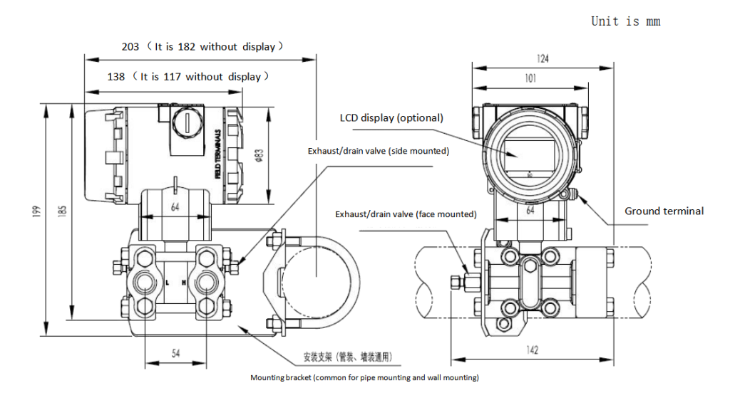
Outline dimension
Свяжитесь с нами!
Сопутствующие товары
Сопутствующие товарыпартнер
партнер
 скачать
